The picture illustrates at the top of the camera a sticker with FCC.... you must remove this sticker and then you see a small hole. With a small screwdriver (1 mm) or a paperclip you must push in the hole to open the quickcam. You must push a small handle internally in the camera and then with a bigger screwdriver you can separate the housing.
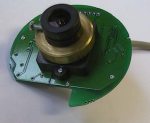
This picture illustrates the internally of the camera.
You can take now the print circuit board of the camera. Precautions! The electronics is CMOS-type, it can be damaged by static electricity.
At the back-side of the print-cicuit board (component-side) you can see 2 small screws. You must remove this screws for removing the lens-part.
This picture illustrates the several parts of the lens-system, also an IR-filtre.
This image illustrates the CCD on the other side of the PCB.
This picture illustrates the electronics in the centronics-connector. Here you can see the CXD1172-AM 6-bit A/D convertor of SONY. and the video-processor PIC15C65 from MicroChip.