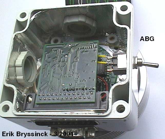
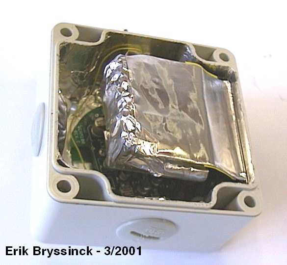
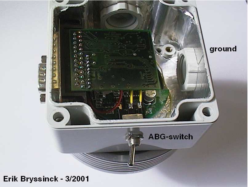
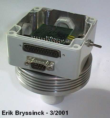
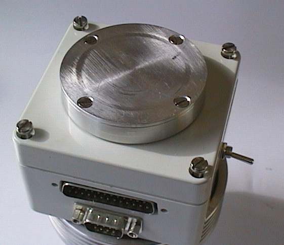
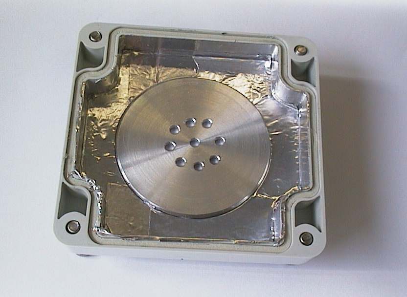
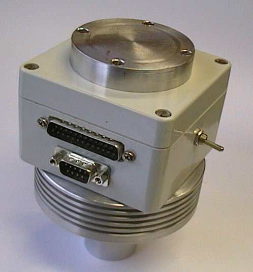
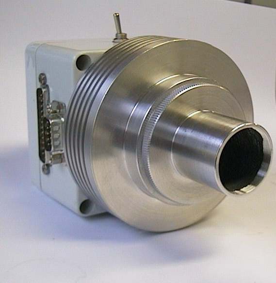
On the pictures above , you see the new design. Remeber, we keep just 1 thing in mind: get rid of the herringbones!
Silicagel dessicant
the silicagel dissicant is placed in the top of the housing.
Also we placed the adhesive aluminium-foil in the top of the housing.
So, thats don! We can close the housing and place for a 15 minutes inert dry gas on the camera. The tests can start!
Camera build and ready for testing
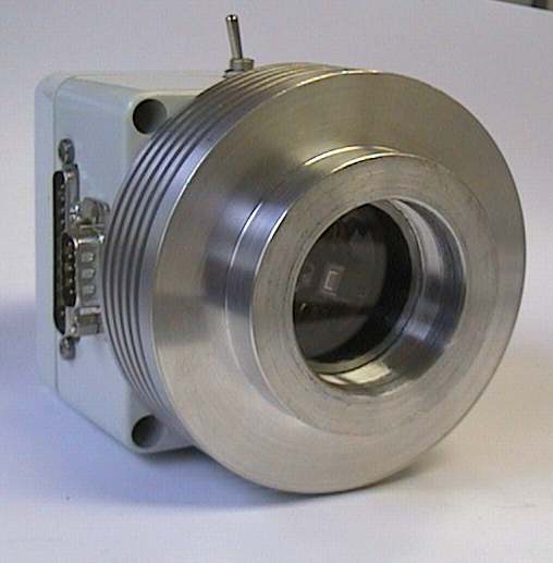
You can see the 2 connectors: one is the original D25 connector. The other is a new connector for the 5V supply, peltier supply and the temperature sensor.
View of the front with eyepiecemounting device.
view of the front without the eyepiecedummy. So i can place my foto-lenses on the camera for wide view prictures.
Copyright - Erik Bryssinck - 7 maart 2001
COPYRIGHT Nothing of this site would be used for publishing, commercial use without permission of the author.
We must take care by placing the alu-foil in the plastic box. Al the pieces must have a good electric contact to eatchother.
On the camera circuit board we can locate a 'gnd'-connection. All the shielding must electrically connected to 1 point. Next parts are connected to this point:
The cold side of the peltier.
the basic heatsink and the hot-side of the peltier
aluminium-foil (is placed between the ABG-switch and the alu-foil.)
I have placed the ADC circuit board with the ADC in the original connectorhousing, but with a saw shorted. I shielded the connectorhousing with the same adhesive aluminium-foil and make a electric connection wtih the shield of the housing. You can see taht on picture 3 above.