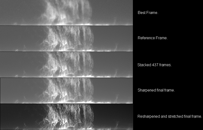
How I process Solar prominence frames in RegiStax 5.
(by Eric Roel)Introduction.
Since RegiStax appeared in
2001, we imagers
started to use this incredible software. At that time, most of the now
known as
“High Resolution” imagers, started taking video streams with all sort
of
camcorders and webcams like the famous workhorse Philips ToUcam. Soon
we all
were using the first versions of Corīs RegiStax, exploiting their ever
growing
features. I must say that without the webcams and without programs to
align and
stack the frames, we would not be where we amateurs are standing today.
At that
time many amateurs were producing images that equaled and very soon
surpassed
all the images professional observatories had made since
astrophotography started.
Amateurs started to be leaders in those chores and even got close to
the
results obtained with the Hubble Space Telescope.
Circa 2001, I started to pester
Cor Berreboets
with questions, with suggestions, etc…, and soon I was invited by him
to join a
fraternity of just a few guys around the world as beta testers.
Suddenly
versions R2 and R3 became rapidly overwhelmed with famous version R4,
multiple
alignment points were born and a new revolution in imaging started.
Amateurs
were getting incredible high resolution images of the Moon, the Planets
and the
Sun never equaled before.
Then again after a long dormant
period for us
testers, Cor was again ready for a new version, a version that now has
features
that make it a more incredible tool.
I wanted to make this brief
introduction
because as one of the beta testers, I personally want to thank and
congratulate
Cor, for taking in account every suggestion or even every crazy idea
from us,
and then worked on them until fully developed and functional.
Finally, I also want to
congratulate and thank
all of my fellow beta testers for being such good friends, always
trying to
help and cooperate with ideas, even that we live in different
continents, have
different cultures, different languages, different time zones, to all I
thanks
for your efforts.
Some
thoughts about the image picked to explain my workflow.
I did choose an avi stream of
the Sun recorded
the 8th of November 2008, because it was taken in medium to good seeing
conditions. The instrument used was the old 6” f/12 Astro-Physics
“Superplanetary” triplet refractor, working at (+) f/30 (5.1” ERF +
2XBarlow +
Telecentric + Daystar ATM 0.45 A° H-alpha filter with a homemade tilter
+
DMK31). The camera resolution was set to 768x768 pixels and 2000 frames
were
taken at 15fps, starting at 10:04:25 am. CST and finishing 2ī13” later.
Solar prominence imaging is
tricky due to
several factors like, daylight low and high atmospheric turbulence, the
subtle
tendrils that conform the protuberance, the continuous change of the
developing
prominence, the very uneven dynamic background created by the Hydrogen
monochromatic light, dispersion from the etalon itself as also from
high
atmospheric humidity, the mechanical tilt of the etalon that distorts
the
image, the high gain
settings needed
for the camera to record dim prominences against an uneven background ,
all that results in
a difficult and
noisy image.
I have tried to make my
workflow as easy as
possible and I must say, that it does not work always, you have to get
the
feeling for every avi stream taken, each is different and therefore it
must be
dealt individually, so for this example, I feel that the workflow shown
is the
one I like better for this particular avi stream.
1- SELECT.
From the 2000 frame 1.09 GB avi
stream, I
picked the best or let’s say, one of the best frames by moving the
lower
slider. In this case frame number 745
was chosen.
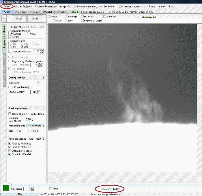
Figure 1.
2- ALIGN.
I took a few moments to analyze
the image I had
in front before clicking on the align tab,
by moving the lower slider slowly from frame 1 to frame 2000 several
times, and
watching for drift, for changes in the structure of the prominence, for
the
turbulence pattern, etc… In this case, I felt that the big prominence
could be aligned
and stacked with just 2 alignment points, by using an alignment
box size 256.
In prominence imaging, I have
found that it is
better to use just as few alignment points as possible, so not to
produce the
dreaded seams and changes in intensity from adjoining alignment points
that
show when you have less or more frames stacked on different alignment
sections.
This problem most of the time
appears when
using many aligning points on an object like a prominence, that has
very low
contrast and that is dancing all the time in front of a very light and
uneven
background. (On the moon, the planets or in solar disc surface feature
imaging
this is not a big problem, but it sure is in solar prominence imaging).
From the Alignment
Options tab, I did
set:
a) Alignment method to Multi,
b) Alignment box to 256.
c) Quality settings to Gradient2.
d) Lowest quality to 90.
e) Click on pre-blurring.
f) On tracking
settings clicked to track
object, processing area clicked to 1024
and checked all auto
processing buttons, the features not mentioned were left as default.
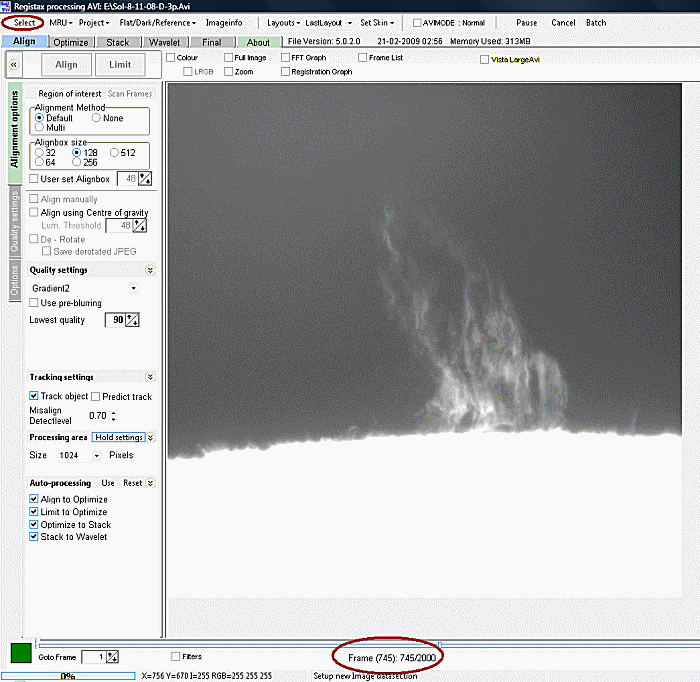
Figure 2.
Placed the first alignment box on the lower part of the prominence and after that, the second box on top of the first one, trying to cover all the prominence and to anchor them on some feature that shows some contrast, if happy with it, clicked on the Align tab, if not, cleared the alignment points by clicking clear on the multialign panel at right, and did it again until satisfied. (Figure-2)
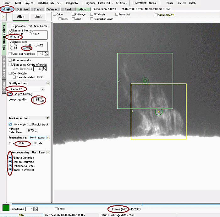
Figure 3
3- REFERENCE frame.
After all the frames were
aligned (figure 3),
clicked on LIMIT tab to start making the default 50 frame Reference Frame, that will
become the sample for all the
frames to be stacked further on the process.
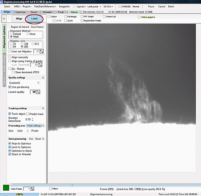
Figure 4
Before the reference is
ready to serve as the
sample for all the frames that will be stacked and optimized (figure
6), it has
to be sharpened a bit with the Wavelet tool,
so generally I use it in Gaussian and linear
mode and just use layer 1 to get enough resolution
from the sample, in
the case shown it is 65%.
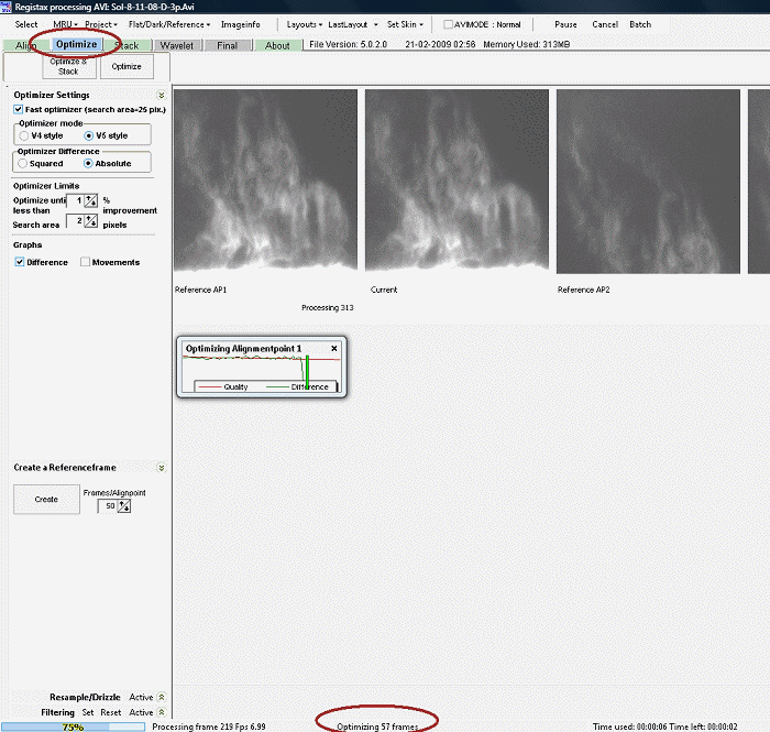 Figure 6
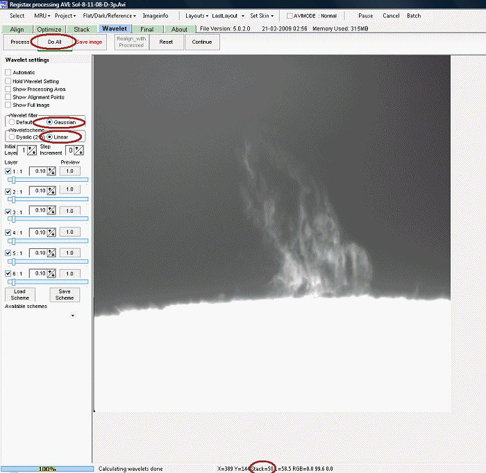
Figure 7.
After the Reference Frame
process is finished, we then click on Continue to
start the Optimizing process.
4- OPTIMIZING.
After you click on Continue,
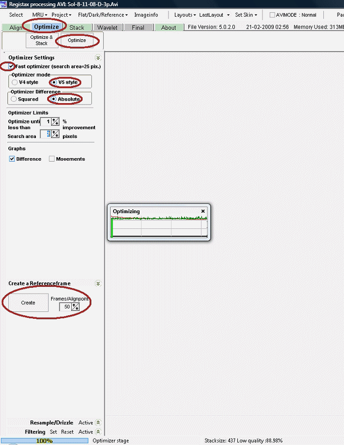
one has two
choices, one is to click on the Optimize tab, and
the other on the Optimize
& Stack tab. Choose the Optimize
tab, so to set these optimizing
parameters:
a) Set
the optimize setting to fast.
b) Opt
for v5 mode by clicking on the button.
c) Opt
for absolute.
d) Leaving
the rest of the parameters as default.
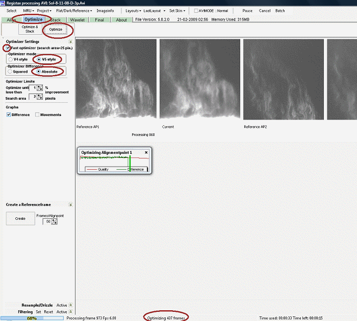
Figure 9.
When optimizing is finished,
you are ready to
begin stacking the frames you decided to use for your final image.
5- STACKING.
After opening the Stacking tab we have to set the
parameters that are needed for
stacking our frames, in this case:
a) Normalize
intensity over frames.
b) Stackgraph for further tweaking.
When looking at the Stackgraph Panel, you will find 2
sliders, the one on the top graph
can be moved horizontally and the one on the lower graph vertically.
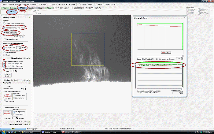
Figure 10
I did not move the sliders,
because the graphs
show a rather flat and not overly spiky result. Though I suggest that
it is
worth reading thoroughly the latest manual, to understand how these
tools work.
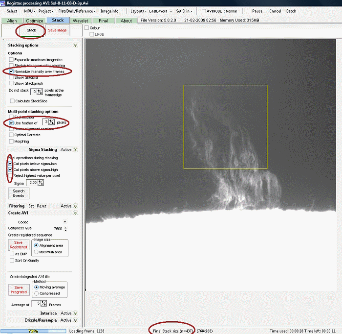
Figure 11
Once the frames are stacked to
the parameters
set from the beginning, then you are ready to enhance the resultant
image, so
click on the WAVELET tab.
6- WAVELET.
As soon as you press this tab,
you will find
the final stacked image enhanced to the value you choose for the Reference
Frame. I normally use on this type of objects just Layer
1, so to get the
finest details possible
on the final stacked image.
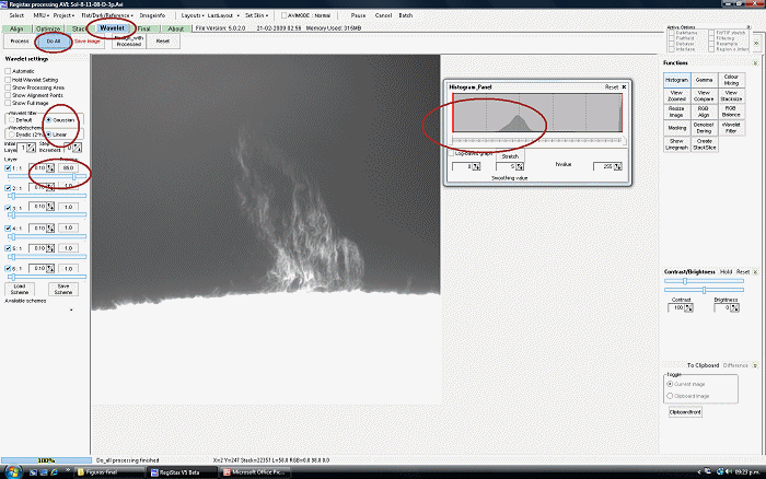
Figure 12.
Analyzing the final stacked
image, you find
that it can handle a bit more sharpening without getting too noisy and
also
that it needs a stretch to normalize the image, so for that we have to
use the Histogram
tool to see how far we need to bring up the black point. When happy
with the
result you can just save your image in the format you wish, or tweak
the final
image a bit more by clicking on the FINAL tab.
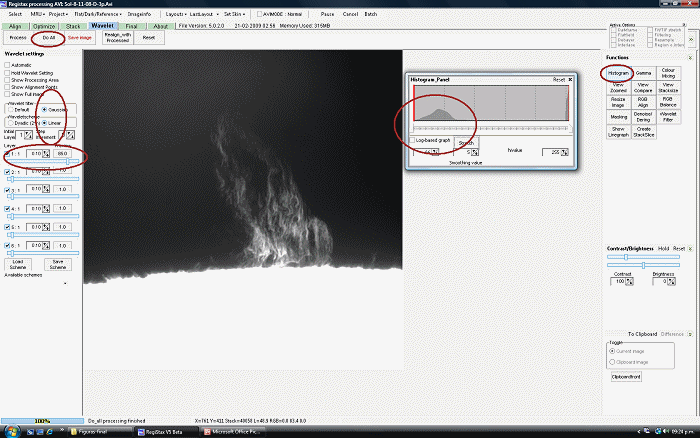
Figure 13
7- FINAL.
Usually I donīt leave as the
final image the
one shown, because after recording the prominence avi stream, I also
take an
avi stream of just the solar surface (without showing the prominence),
so later
I can make a composite with the 2 resulting images, giving the overall
visual
appearance of Prominence plus the solar disc detail. This procedure
uses other
well known processing programs, to further tweak the resultant image by
increasing sharpness, increasing contrast, reducing noise, removing
gradients,
etc…, programs that are not part of RegiStax5.
Nevertheless, I used the FINAL tab to give the RegiStax final
image an antique tint, by
using the saturation and hue sliders, so to keep out the harsh look of
the
bright solar disc, the dimmer prominence and the uneven background.
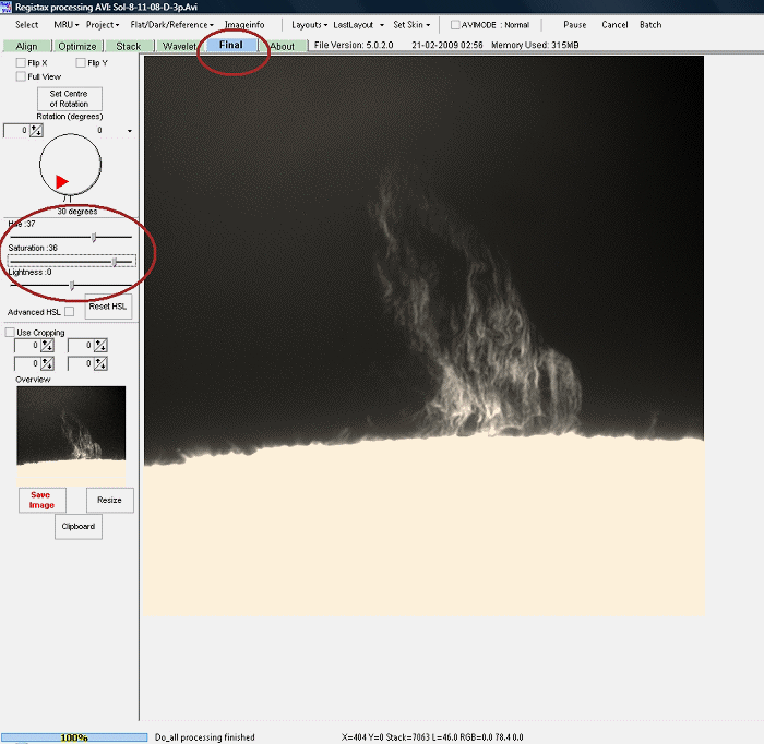
Figure 14
