
I have been fortunate to be a part of the development team for Registax 6 from day one. Having used the beta software for over 4 months, I have come up with my own set of steps to process raw frames to stacking and wavelets. I plan to share those steps here to help the reader get past the basic learning curve of Registax 6. One of the things the reader will observe is that, compared to Registax 5, there are fewer steps and Registax 6 works much faster. Cor will no doubt outline a full list of improvements and changes he has made with 6 versus 5. Below will be my processing steps. These are by no means the only or even the best way to process. They are simply the steps I use. The reader can use these steps to develop his own method. The most important thing is not to be afraid to experiment!
I capture my data as 8 bit bmp files. I have been doing this for several years and do so for a couple of reasons. First, I feel more in control of each individual frame if I can access by itself. Second, I like to run the frames through Ninox by Anthony Wesley. This software crops the frames to a more manageable size (like 400x400) and centers the brightest object in the frame. I have tried all the readily available stacking programs and found that this step does make a noticeable difference. I drag and drop my bmp frames onto Registax. After 5 years of doing this I have gotten pretty good at it.
So, let’s get to it!
My first step is to drag and drop my frames onto Registax (Figure 1). Once you do that, you’ll see the screen shown in Figure 2. At this point you have a couple of decisions to make. For an object like Mars or Saturn, I set the Minimum distance between to it’s lowest value (10). For Jupiter I’ll set it to 15, and for the sun or moon I typically set it to 30 or 35. The number of alignment points will differ based on the size of the object on your image. In general, with a given sized object, the lower the Minimum distance number, the more alignment points (APS) you will have. As far as the number of APS, I find that there is a point of diminishing return. I have processed a solar image with 600 APS and 175 APS and found no difference in the final image. More points take longer to process, so you have to decide what looks right. The next box, Min distance from edge, can be left at it’s default value, 20.
At this point I click the Show Prefilter box and click Normalize. This seems to help data that varies in brightness and since I’ve seen no problems using it with good data, I just always use it. Again this is your choice.
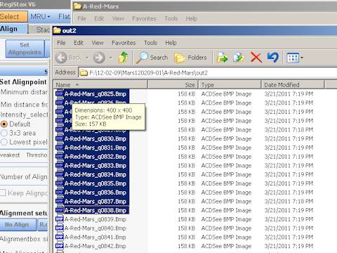
Figure 1
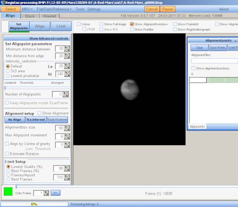
Figure 2
So I click the Set Alignpoints button and Registax will select the points. Registax tries to make sure you are selecting strong points, so the weakest-strongest slider moves 10% forward. See Figure 3.
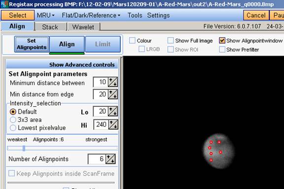
Figure 3
You will see from the figure
the 6 APS selected and the slider moved to the right a bit. Six points will
work fine with this Mars image. I like to have about 30 points on Saturn, 70-75
on Jupiter and 150-200 on the moon or sun. You can add more points manually
simply by left-clicking on the image at the spots you want additional points,
and rt-clicking on unwanted points removes them. It is best not to place APS in dark areas or areas with no contrast.
For me, I’m ready to click the Align button. You will see the progress bar move across the bottom of the screen and the timer on the right gives you elapsed time (Figure 4).
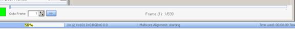
Figure 4
Once this is done, observe the
Goto Frame box at the bottom of the screen (Figure 4).
This box tells you how many frames will be stacked. Either move
the slider to select the desired number of frames, or type in the
desired number. I use the Best Frames option. Again, you
should experiment to see what works best for you. If you
set 100 frames with 100 frames/AP you will stack more frames than when
using 100 best frames.
Click the Limit button
and you will see the screen in Figure 5.

Figure 5
I leave the values as you see
them in the figure. Then I click the Stack
button (next to the “Save Image”) button. In a few seconds the
stacking will be done. The amount of time to stack will depend on
the size of the image, number of frames and number of
alignpoints. See Figure 6.
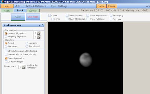
Figure 6
At this point, I click the
Wavelet tab and save my raw data.
Wavelets
Cor has made some changes to
the wavelet section. Most of it is over my head, but basically he added a
denoise box for each layer. From his description, this is an extension of his
noise trapping in layer 1 from Registax 5. There will be more detail with the
release. To use the denoise settings you must use Gaussian
wavelets. I got my settings file from Sylvain Weiller and made
some slight modifications to suit me. These settings are
guidelines only, just something to get you started. Look
carefully at Figure 7 to see the Denoise and Sharpen
settings for each layer. Notice the quality of the image compared to Figure 6.
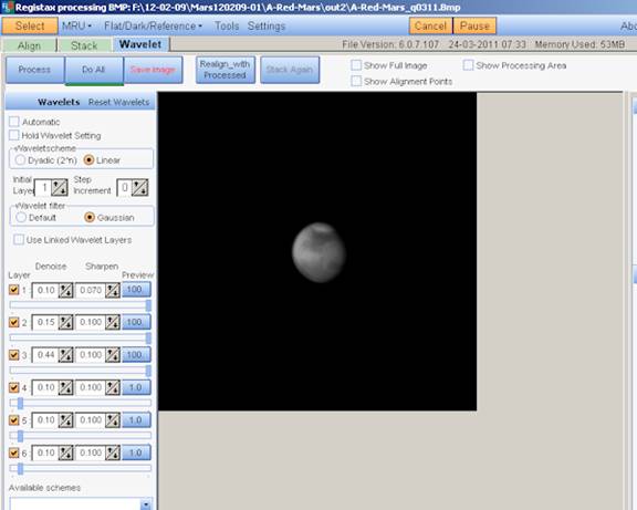
Figure 7
Looks pretty good doesn’t it? Now I’m going to click one more box. Locate the Use Linked Wavelet Layers box just below the Gaussian and Default bullets. Look at Figure 8 and see what happens when I click that box.
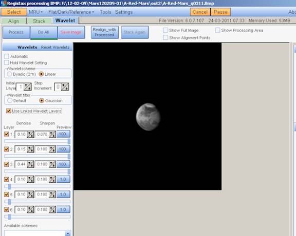
Figure 8
Pretty dramatic difference,
huh? That illustrated the power of the Denoise and Linked Wavelet Layer
features. You can experiment to find values that are pleasing to you. Figure 9
has a slightly different set of values for wavelets so you can see how changing
the wavelet settings affect the final image.

Figure 9
Well, that’s about all I do.
On my quad-core 2.8 GHz system, this process from drag and drop to wavelets
takes less than 3 minutes. Of course, now I’ll save the processed image and
bring it into my post processing programs to give it the finishing touch.
I hope these guidelines help you to develop your own processing routine and maybe help you produce your best images ever.